Thursday 23 May 2013

Piezoelectric Force Sensor

A piezoelectric sensor is a device that employs the piezoelectric effect for the measurement of pressure, acceleration, strain or force by transforming them to an electrical signal. It is the most common dynamic force and acceleration detector. It is appropriately named after the Greek word piezo (which means "to squeeze”) because a piezoelectric sensor generates a voltage when it is "squeezed" by a force that is proportional to the force applied.

Working Principle

An amplifier is used to convert the high impedance electrical signal (produced by the piezoelectric) to a low impedance signal. This makes it apt for use with an instrument like a digital storage oscilloscope. Digital storage of the signal is obligatory in order to enable analysis of the signal before it decomposes. Cross-sectional view of a typical piezoelectric force sensor is shown in the figure below:
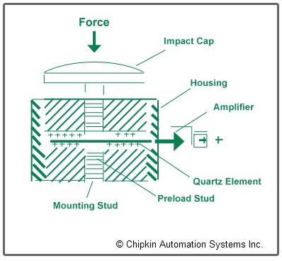
Piezoelectric Force Sensor Working Principle


Discharge Time Constant (DTC)

It is defined as the time needed for a sensor or measuring system to discharge its signal to 37% of the original value from a step change of measurand. This is accurate in case of every piezoelectric sensor, whether the operation is force, pressure or vibration monitoring. The DTC of a system is directly linked to the low frequency monitoring capabilities of a system. In the case of force monitoring, it becomes extremely significant as it is frequently desired to carry out quasi-static measurements.

Main Features

Fast response, ruggedness, stiffness comparable to solid steel, extended ranges and the ability to measure quasi-static forces are standard features coupled with piezoelectric force sensors. Following are the key features of piezoelectric force sensors:
  • A piezoelectric force sensor is approximately as rigid as a comparably proportioned piece of solid steel. This stiffness and strength enables these sensors to be directly inserted into machines as part of their structure.
  • Their rigidity bestows them with a high natural frequency, and their equivalent rapid rise time makes them ideal for measuring such rapid transient forces as those generated by metal-to-metal impacts and by high frequency vibrations.
  • To make certain accurate measurement, the natural frequency of the sensing device must be considerably higher than the frequency to be measured. If the measured frequency comes close to the natural frequency of the sensor, measurement errors will result.

Applications

Based upon the application needs, dynamic force can be measured as either
  1. Compression,
  2. Tensile, or
  3. Torque force
Applications may incorporate
  • The measurement of spring or sliding friction forces,
  • Chain tensions,
  • Clutch release forces,
  • Peel strengths of laminates, labels, and pull tabs

Limitation

The basic point of distinction between piezoelectric devices and static force detection devices such as strain gauge is that the electrical signal generated by the crystal decays quickly after the application of force. This disparity renders these devices inappropriate for the detection of static force.

Automation System Integrator

Protocol Gateways

Tuesday 23 April 2013

Pressure Transducers


Types of Pressure Sensors


The demand for pressure measuring instruments arises with the advent of steam age. Mechanical methods of measuring pressure such as Bourdon tubes or bellows, where mechanical displacements were transferred to an indicating pointer were the first pressure instruments. Initially, these tubes were constructed of glass, and scales were added to them as per requirements. However, these mechanical motion balance pressure measuring arrangements were large, cumbersome, and not well suited for integration into automatic control loops. Consequently, as control systems evolve to become more centralized and computerized, these devices were replaced by analog electronic and, more lately, digital electronic pressure transmitters. Pressure transmitters or transducers are ready to use instruments employed for measurement of pressure. These are OEM transducers with
  • pressure port
  • integrated compensation resistors
  • a cable or connector
The terms pressure gauge, sensor, transducer, and transmitter can be used interchangeably. Majority of modern pressure sensors operates on piezoresistance principle. Due to pressure, a material generates electricity at a certain rate, which leads to a specific level of charge flow related with a specific level of pressure. This charge is supplied to a wire which leads to a control panel and display for human analysis.


Pressure Transmitter


It is a standardized pressure measurement package which includes following three fundamental components:
  • a pressure transducer
  • its power supply,
  • a signal conditioner/retransmitter used to transform the transducer signal into a standardized output
  • In pressure transmitters, process pressures can be transmitted using
  • an analog pneumatic (3-15 psig),
  • analog electronic (4-20 mA dc),
  • or digital electronic signal
When transducers are directly interfaced with digital data acquisition systems and are positioned at some distance from the data acquisition hardware, high output voltage signals are preferred and these signals must be guarded against both electromagnetic and radio frequency interference (EMI/RFI) when traveling longer distances.

Bacnet Explorer


Tuesday 26 March 2013

Types of Thermocouples


Thermocouples can be manufactured from a diversity of metals covering a temperature range of 200 oC to 2,600 oC. Various combinations of metals i.e. calibrations exist for thermocouples. There are approximately thirteen types of standard thermocouples available in the industry and out of them eight have been designated with an internationally known letters. The eight designated thermocouple types are listed below:
  1. Type K – This type of thermocouple is made up of Chromel-Alumel. It belongs to the chromium-nickel aluminum group and has a fairly linear e.m.f./temperature curve.
  2. Type J – This type of thermocouple having limited temperature range is made up of Iron-Constantan.
  3. Type E – It is made up of Chromel-Constantan and offers great sensitivity. It is primarily used in cryogenic i.e. low temperature range. Being a non magnetic type, it proves to be advantageous in variety of applications.
  4. Type N – It is made up of Nicros-Nisil and offers excellent thermoelectric stability. It is extremely resistant to high temperature oxidation.
  5. Type T – This type of thermocouple is made up of Copper-Constantan. It is found extremely useful in food, environmental and refrigeration applications.
  6. Type S – It is made up of Platinum rhodium
  7. Type R – It also contains Platinum rhodium and somewhat identical to type S
  8. Type B - It is an extremely stable thermocouple made up of Platinum rhodium only. Its output is found to be very small at room temperature and offers less sensitivity in the lower range.
The above thermocouple types can be categorized into two groups i.e. Base metal and Rate or Noble metal. Type K, J, E, N and T fall into the Base metal category whereas Type R, S and B come into the Noble metal category.
In general, there are four classes of thermocouples which are mentioned below:
  1. Home body class which is also referred to as Base metal Type. The temperature range for these types of thermocouples varies from -200°C to 1200°C.
  2. Upper crust class, also known as Rare metal or Precious metal or Noble metal Type. The temperature range for these types of thermocouples varies from 0°C to 1600°C.
  3. Rarified class, also known as Refractory metal Type
  4. Exotic class which consists of various tungsten alloy thermocouples and many other standard and developmental devices. It is typically designated by Type W.
Each thermocouple type or calibration has a specific range of temperature and environment. However, the maximum temperature possible depends upon the thermocouple wire diameter. The most preferred types of thermocouples are found to be K and N types since they perform well at high temperatures, whereas another industry preferred thermocouple is T type as it offers high sensitivity, low cost and simple operation.

Protocol Gateways

Friday 8 February 2013

Force & its Effects


Force & its Effects Definition 

A quantity competent enough to modify the size, shape, or motion of an object is termed as force. In other words “A force is an influence (such as a push, gravity, or friction) that causes an object either to change its velocity or to store energy through deformation”. Since force is a vector quantity, it has got both direction and magnitude. In case, a body is in motion, the energy of its motion can be quantified as the momentum of the object i.e. the product of its mass and its velocity. When the body is free to move, its velocity will be changed by the action of a force.

Units of Measurement

The precise measurement of force is significant in many areas, like engine thrust determination, the weighing of large structures, and materials testing. The magnitude of a force is measured in:
  1. Newtons (In the SI system): One Newton is defined as the force required to accelerate a mass of one kilogram at a rate of one metre per second, per second
  2. Pounds (In the British/American system)

Basic Forces

Four basic forces found in nature are:
  1. Gravitational Force: It is the force of attraction between any two bodies in the universe. It is the weakest of all and also the easiest to observe. It is always attractive and has an infinite range.
  2. Magnetic Force: It can be the force between two magnets or force on a magnet placed in a magnetic field. It can be either attractive or repulsive.
  3. Strong nuclear Force: It is a strong force with a short range. It is a non-central force which acts within the nucleus. It is not directed along the line joining the centres of the interacting particles.
  4. Weak nuclear Force: Its range is shorter than the strong nuclear force and this type of force is considerable only for certain nuclear processes like radioactive beta decay.

Pressure

It is the ratio between force acting on a surface and the area of that surface. It is measured in units of force divided by area:
  1. Pounds per square inch (psi)
  2. Newtons per square meter, or Pascals
Whenever an object is subjected to an external stress i.e. pressure with the aim to cause a reduction in its volume, this process is called compression. The majority of liquids and solids are practically incompressible, whereas gases are not.

Boyle's Law

It is the first Gas Law which states that the pressure and volume of a gas are inversely proportional to one another i.e. PV = k, where P is pressure, V is volume and k is a constant of proportionality.

Charles' Law

It is the Second Gas Law which states that the volume of an enclosed gas is directly proportional to its temperature i.e. V = kT, where T is its absolute temperature.

Third Gas Law

According to this law, the pressure of a gas is directly proportional to its absolute temperature i.e. P = kT. After combining the three relationships we get the ideal gas law i.e. PV = kT. This approximate relationship holds accurate for many gases at relatively low pressures and high temperatures.

Monday 7 January 2013

Analog to Digital Converter


An analog-to-digital converter (commonly abbreviated as ADC, A/D or A to D) is a device which converts continuous signals to discrete digital numbers. In general, an ADC is an electronic device basically employed for transforming an input analog voltage or current in to a digital number proportional to the magnitude of the voltage or current.
An analog signal is continuous in time and it is required to convert this to a flow of digital values. For that reason it is essential to define the rate at which new digital values are sampled from the analog signal. The rate of new values is called the sampling rate or sampling frequency of the converter.

Analog to Digital Converter - Continued

Thursday 3 January 2013

RSLinx Diagnostic Tools


RSLinx includes a wealth of diagnostic information to assist us in analyzing our system. Whether it's trouble-shooting a communication problem or analyzing network throughput, RSLinx provides the needed information. Diagnostics fall into following three major categories:
  1. Networks: Diagnostic counters track server information such as messages sent, messages received, messages acknowledged, communication errors, and timeouts. Performance counters give throughput in terms of packets/second.
  2. Station: Diagnostic counters indicate information for a selected station such as messages sent and received, message retries, and packet errors.
  3. OPC/DDE: Multiple dialogs for DDE clients, OPC Groups, Optimized Packets, and OPC/ DDE server connections display diagnostic information specific to the category. A Communication event log displays information specific to an OPC/DDE transaction. 

Tuesday 11 December 2012

RSLinx


RSLinx Classic is an inclusive communication server which provides plant-floor device connectivity for a wide variety of Rockwell Software applications such as
  • RSLogix 5/500/5000
  • RSView32
  • FactoryTalk View Site Edition
  • FactoryTalk Transaction Manager
Besides, numerous open interfaces are provided for third-party HMI, data collection and analysis packages, and custom client-application software. RSLinx Classic is capable enough to support multiple software applications at the same time, communicating to a range of devices on many different networks.
RSLinx Classic 2.x is now associated to RSLinx Enterprise, a new product that provides supreme connectivity to Logix processors. RSLinx Enterprise provides data services for distributed FactoryTalk View Site Edition products, FactoryTalk Transaction Manager, FactoryTalk Historian, and FactoryTalk Metrics applications.
One can communicate from anywhere to anywhere using RSLinx Classic. RSLinx is available in multiple packages to meet the demand for a variety of cost and functionality requirements.

RSLinx Benefits